
John Errington's Experiments with an Arduino
Controlling DC motors: Sensing current
Why sense the current? Sensing the current tells us a lot about what the motor is doing.
The mechanical power Pm supplied by the motor is given by
Pm = M*w, where M is the torque and w the rotational speed.
If we ignore frictional loses the mechanical power Pm is equal to the electrical power Pe supplied to the motor - which is
Pe = V*I Watts.
Now if V is volts and I is amps the units we need for M and w are M = Newton-metres and w= radians per second.
However more convenient units for torque and rotational speed are oz-inches and rpm (revolutions per minute).
Applying the math to convert these units gives us a conversion factor of 0.00074.
Example 1
If our motor is turning at 3000 rpm with a torque of 2 oz-in the mechanical power is 3000 * 2 * 0.00074 = 4.45 Watts.
So if our motor was being driven from a 12V supply we would measure a current of 4.45/12 = 0.37A.
Fault diagnosis
Suppose we are using a motor with a supply of 12V to drive a CPU cooling fan. Normally the current is just over 0.4A so a power of 5W.
If the current has fallen dramatically - to around 0.05A say - that would tell us the shaft coupling or a fan blade had failed.
If the current had INCREASED it would show excessive demand on the motor, possibly because of a bearing failure or dirt stalling the fan blades.
How to sense the current

For DC applications the simplest way to determine the current being drawn is to insert a resistor in series with the supply to the motor, as shown here. We can then use Ohm's Law to show Vs = Im R whence Im = Vs / R
We know the power to the motor is Pe = V1 * Im;
however because we have inserted a resistor the voltage is no longer constant. V1 is Vcc - Vs. Ideally we would like to operate the motor from a constant voltage source (Vcc). The best we can do here is to use a very small value for R.
Example:
Suppose the maximum current we will allow through our motor is 2A.
If we pick R3 = 0.1 ohms then for Im = 2A we get Vs = 2A * 0.1 ohm = 0.2V
Alternatively if we measure Vs = 0.04V we can calculate Im = Vs / R3 = 0.04 / 0.1 = 0.4A
High side and low side sensing
We can insert the shunt resistor as a series element anywhere in the circuit. The diagram above shows the shunt in the connection to the positive supply. (high side sensing)
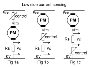
Here we have three different configurations in which the sensing element Rs is inserted in series in the connection to the zero volt rail. We call this low side sensing.
Low side sensing brings with it some problems.
Remember the Arduino (or any other microcontroller system) uses ground referenced inputs and outputs. Figures 1a and 1b show a ground referenced sense voltage - so thats easy to measure; however the control element - perhaps a transistor or FET - is NOT ground referenced, giving us problems with the control circuit.
In Figure 1c
the control element IS ground referenced - but the sense output Vs is not.
High side current sensing
 Here we see the shunt in the high (positive) side of the motor.
Both terminals of the Vs output are very near the Vcc supply rail - and that may well be outside the acceptable input voltage for an Arduino or similar device. However by adding a few extra inexpensive components as shown below we can generate a more convenient single-ended ground referenced voltage that is proportional to the motor current.
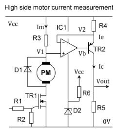
High side sensing with ground referenced output

This circuit shows how we can implement high side current sensing and generate a ground referenced output. The way it works may not be immediately obvious so I've done a simple analysis below.
Remember an ideal operational amplifier is defined as follows:
- input resistance infinite; (so there is no current into the input terminals)
- open circuit gain infinite; (so there is no voltage difference between the + and - inputs)
- output resistance zero;
- bandwidth infinite.
Lets assume our transistor is also ideal, with an infinite common emitter current gain - so Ie = Ic
How it works
 V1 measures the motor current as Im R3. V2 is Ie R4; and from (1) above V2 = V1;
so Ie R4 = Im R3 and by rearranging, Ie = Im R3 / R4
Vout = Ic R5. But Ic = Ie, so Vout = Im R3 R5 / R4
Example values
Suppose for a maximum motor current of 0.5A we choose R3 = 0.1 ohm; R4 = 100 ohm and R5 = 1k.
Then Vout = 0.5 * 0.1 * 100 /1000 so Vout = 0.5V
Component considerations for practical circuits, typical values, and measurement errors
Shunt resistor R3:
Typically we choose a value of shunt resistor that will give a voltage of 0.1V at the maximum rated current Im of the motor. It will then need a power rating of 0.1v * Im Watts.
R4 and R5
The maximum voltage across R4 will be 0.1V, so a "standard" value of R4 = 100 ohms will give a current of Ic = 0.1V / 100 ohm = 1mA.
We can now choose R5 to give the desired voltage output; we MUST choose a value such that V3max +VR4max + 1.0V does not approach Vcc.
(we allow 1.0V for the correct operation of the transistor)
For a 5V supply, with values already given Vcc - Vr4max - 1.0V = 5.0 - 0.1 - 1.0 = 3.9V
so we could choose R5 = 2k0 to give a full scale reading of about 2V which is convenient for our Arduino ADC.
Operational Amplifier
The op amp will need to work with both inputs, and its output, very close to the positive supply rail voltage; most CMOS op amps are suitable - however they usually require a single-ended supply voltage not exceeding 5V. For example the MCP6042 dual CMOS Op Amp can run from a single supply of 1.4V - 6.0V and provide an output swing from rail to rail.
The diagram below shows how we can adapt the circuit to suit higher supply voltages.
Transistor
Unless working with large voltages most high gain pnp transistors will work fine in this application. Taking an example at random, the 2N3906 has a maximum voltage rating of 40V. As we are using a collector current of around 1mA we need not worry about the power rating as even with a 40V supply we would see less than 40mW.
Measurement errors
This diagram shows how by adding a simple zener diode we can ensure the supply voltage to the op amp is not exceeded. We just choose Vz + 5V =Vcc. R6 provides a little bias current to the zener.
Measurement errors.
The main sources of measurement error lie in the resistor values, particularly the shunt resistor. These errors are fixed, so its easy to correct for them by suitably scaling our readings.
Calculation of the actual mechanical power delivered by the motor is less easy, as we need to allow for electrical ("copper") losses, magnetic ("iron") losses, and frictional losses in the drive train.
Typically permanent magnet motors have efficiencies over 85%, with larger motors being more efficient.