John Errington's tutorial on Power Supply Design
Feedback
Line and contact resistance
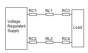
 In the circuit shown here RC1 - RC4 represent resistances introduced by making connection between wires and the supply or load; and RL1 & RL2 represent the resistance of the connecting wires (or tracks).
Lets look at the impact of these resistances and how this can be avoided.
Our "precision voltage supply" can have a resistance lower than 1mohm. (0.001 ohm)
The wire used to connect the supply to a load will introduce a resistance. For example the resistance of 20AWG copper wire is 26mohm/m. A 10cm length will have R = 2.6 mohm. So RL1 = RL2 = 2.6
Depending on the method used, the connection between connecting wire and circuit may also be of the order of 1mohm.
In this case the total resistance of our connections between supply and load will be around 2*2.6 + 4*1 = 9 mohm.
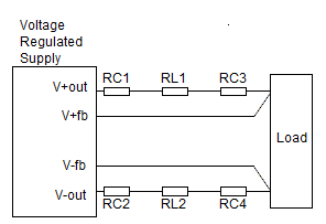
By using a 4 contact method as shown below we can eliminate the effects of these resistances.
Four contact method

Here the feedback connectioons are used to measure the voltage at the load, and it is this voltage which is regulated. As the current in the feedbck loop is very small (typically less than 1mA) the line and contact resistance in the feedback loop can be ignored.
