John Errington's tutorial on Power Supply Design
Choosing a Transformer and Rectifier
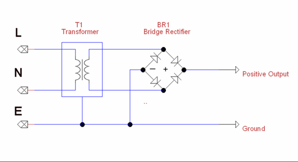
Producing a DC voltage from AC mains involves the use of a transformer and rectifier as shown below. The transformer changes the mains voltage to something better suited to our requirements; and the rectifier removes the negative part of the signal giving an output which only has positive voltages. The diagram below shows a bridge rectifier; a single diode rectifier can be used, but is less efficient; and as silicon diodes are inexpensive the bridge design has become almost universal.
For the purposes of this tutorial I will use as an example a supply with a 12V DC output; however the simple theory will allow you to design supplies for any desired voltge and current. Later sections will use as an example the design for a variable supply of 2A at up to 30V.
Voltage drop in the rectifier
Rectifier: A single silicon rectifier diode in forward conduction develops a voltage of around 0.7V (but can be up to 2V). In general we allow about 2V drop for the bridge rectifier configuration.
Transformer: Losses also occur in the transformer windings; however a transformer rated at 220V: 30V at 10A will usually provide a 30V rms output when delivering the rated current. This means that the voltage when off-load will be higher.
Waveforms around the circuit
 These diagrams show the voltage at different points in the circuit, based on a 240:12V transformer.
Here you can see the output from the transformer. The output is a sinewave centred around 0 volts.
The peak voltage Vpk is 1.414 (square root of 2) times the RMS output - the transformers quoted value.
Eg for a 240V: 12V transformer the peak voltage will be
1.414 times 12 = 17V
 This diagram shows the output from the bridge rectifier.
You can see the negative "hump" from the ac signal above has bee "turned upside down" by the bridge recifier assembly. The peak voltage is now 17V - 2V = 15V.
The RMS voltage is around 10.6V at full load. It rises when the load is reduced. The average voltage is 9.27
You can also see the flat part near zero where none of the rectifier diodes have started to conduct.
 The signal above can be seen as a constant DC voltage of 9.27V with a superimposed varying signal of about 15V peak - to - peak and an average value of 0V.
The rms value of this signal is around 15 / 2 * 1.414 = 5.4V
Example design - choosing components
Specification: Design and build a psu to run from 240V ac mains. It must power a 12V DC motor which runs for long periods of time and in normal use draws a maximum of 2A from the supply.
![]()
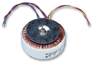
We will need a transformer rated at 12V 2A = 24W or more
Here you can see two possible transformer styles. Either would be suitable.
Both are rated 12V 48W
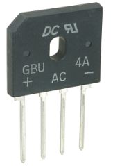 This is a silicon bridge rectifier rated at 200V peak reverse voltage and 4A average forward current. This would be fine.
Heat calculation:
In use there would be a current of 2A and a forward voltage drop of about 0.9V per diode (data sheet), or 1.8V across both.
2A * 1.8V = 3.6 W.
The thermal resistance to air (from the data sheet) is 22 degrees C per watt, so the package would be 22 * 3.6 = 80 degrees above ambient temperature. Thats a bit too warm, so we will add a small heat sink, or bolt the rectifier to a metal case.